Stelios's Place
A place for thoughts and ideas
USB Home Automation
USB Home Automation is a small USB device that uses a PicAxe chip and a cheap AM RF transmitter to control remote switches like the ones made by ArcTech and sold under various brand names like Byron and Elro. It's similar in concept and function with the Telldus TellStick product.
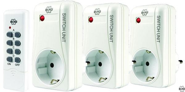
An Elro remote switch device
The idea was to create a device to control my aquarium lights from my computer. This way I could write a software to work as a time scheduler in order to turn the lights on and off based on a time table. You can see the complete device in the picture below which uses just 5 parts. The cable shown is a cell phone data cable which includes a USB-to-TTL module. You can get similar modules from eBay.
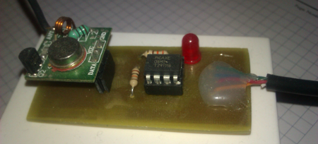
The complete device
The wireless protocol used in this project is known as NEXA. You can have a look at the specification for the protocol here. Searching Google for NEXA protocol will provide additional resources. The code for the PicAxe chip is based in information provided by this Arduino project: http://arduino.cc/forum/index.php/topic,38075.0.html and from help by various folks in the PicAxe forum (see here).
The PicAxe chip is a 08M2 running at 32MHz to better match the timing needs in order to correctly emulate a PT2262 IC (datasheet) functions. I had been checking and testing the timings between the pulses using the Logic Sniffer from Dangerous Prototypes. The RF transmitter used in the project is a TM1000-1 which you can find on eBay. This is a high output transmitter which is ideal since the transmitter will not always be in the same room with the remote switches.
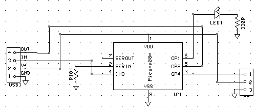
The circuit
Besides the PicAxe chip and the RF transmitter the board requires a couple more components to work: a couple of resistors and an LED. You can check the values of the resistors in the circuit diagram picture. One resistor matches the LED and the other one makes sure that the Serial-In programming pin stays tied down to the ground.
The device communicates with a PC over a USB-to-serial connection from which it gets it's power as well. In my case, I have used an old mobile phone data cable which also includes a PL2303 IC inside the USB plug. The communication protocol is pretty simple and straight forward. You send the numeric ID for the device you need to control and then you send the 1 or 0 in order to turn the plug on or off. The keyboard/character sequence to turn on the device with ID 1 looks like: 1[enter]1[enter]
On each remote plug you need to configure a Group and the unique Plug ID. On the back of the plug there is a DIP switch. The numbers (1,2,3,4,5) are used to define the group and the letters (A, B, C, D, E) are used to define the plug ID. You usually want to set the same group but different plug IDs. The code is configure to handle all 4 IDs from group 01001 and the 2 first IDs from group 01011.
You can get the circuit schematics and the PicAxe code from the Downloads section below. You will need to use the free (as in beer) ExpressPCB software in order to open the files.
Comments and suggestions are welcomed.
~steliosm
Downloads:
Search
Navigation
Fatal error: Uncaught ArgumentCountError: Too few arguments to function toc(), 0 passed in /home/www/steliosm.net/public_html/site/templates/steliosm/template.htm on line 24 and exactly 2 expected in /home/www/steliosm.net/public_html/site/cmsimple/cms.php:432 Stack trace: #0 /home/www/steliosm.net/public_html/site/templates/steliosm/template.htm(24): toc() #1 /home/www/steliosm.net/public_html/site/cmsimple/cms.php(195): include('...') #2 /home/www/steliosm.net/public_html/site/index.php(1): include('...') #3 {main} thrown in /home/www/steliosm.net/public_html/site/cmsimple/cms.php on line 432